


1. Answer 1 (Based on IEC 60909 definition for PSCC)
So what is prospective short circuit current? (IEC 60909)
1.3.3 Prospective (available) short-circuit current
Current that would flow if the short circuit were replaced by an ideal connection of negligible
impedance without any change of the supply
This is one KBAT question for Malaysian Professional Electrical Engineers.
The calculation below is to ultimately calculate the peak current or making current, most websites define the prospective short circuit current as the peak current. However, those definitions kind of differ from the IEC 60909 definition for PSCC.

| SC MVA | ||||
| Utility SC | 50 | kA | 952.63 | MVA |
| Voltage | 11 | kV | ||
| 1.5 | MVA | 26.55 | MVA | |
| Z | 5.65 | % | ||
| Pri | 11 | kV | ||
| Sec | 0.4 | kV | ||
| X | 0.0751 | ohm/km | 4.67 | MVA |
| R | 0.3342 | ohm/km | ||
| Z | 0.342534 | ohm/km | ||
| L | 100 | m | ||
| Z | 0.034253 |
ohm
|
||
| Voltage | 0.4 | kV |
| Peak Multiplier | ||||
| k factor | 2.55 | |||
| Peak Current | ||||
| 3ph Fault at: | Voltage (kV) | Eq. MVAsc (MVA) | Isc (kA) | PSCC = Isc * k factor (kA) |
| Q | 11 |
952.63
|
50 | 127.28 |
| S | 0.4 | 25.83 | 37.28 | 94.90 |
| R | 0.4 | 3.96 | 5.71 | 14.53 |
| EF at | V_Line to GD | Eq. MVAsc (MVA) | Isc (kA) | PSCC = Isc * k factor (kA) |
| R | 0.231 | 3.97 | 17.2 | 43.78 |
You may calculate the single phase to ground fault (EF) at R based on JMPangSeah Fault Level calculation.
===============
How to calculate the fault levels at points S and R
===============
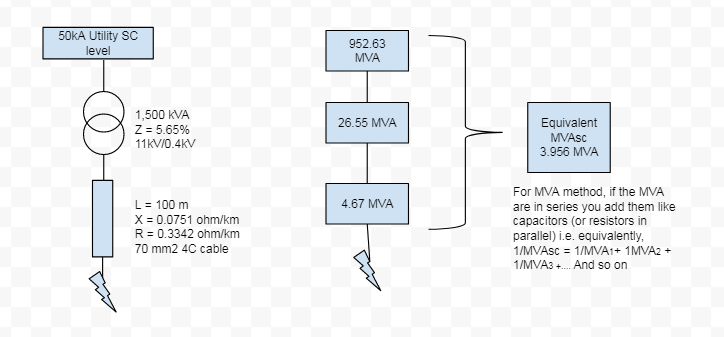
- Tip: Short circuit current must always flow from the source. In this case it is only from the grid (50kA @ 11kV). If you have internal generators, motor or other sources like in a ring circuit, the the current contribution from these sources will make the SC level higher in the system.
At Q, Fault level = 952.63 MVA
At S. Fault level is coming from the grid's 50kA@11kV going through a transformer.
= 952.63 MVA // 26.55 MVA (same like calculating capacitors in series)
= 952.63 x 26.55 / (952.63 + 26.55)
= 25.83 MVA
At T. Fault level is coming from the grid's 50kA@11kV going through a transformer and a cable,
= 952.63 // 26.55 // 4.67
= 25.83 // 4.67
= 3.96 MVA
===============
Answer based on IEC 60909
===============
Considering the definition in IEC 60909 for PSCC - Current that would flow if the short circuit were replaced by an ideal connection of negligible impedance without any change of the supply
Replace cable with ideal connection. So we are only left with Utility 50kA fault current and the 1.5MVA Tx.
Contribution from this source, gives us the final fault MVA of:
= 952.63 // 26.55
= 25.83 MVA
@ 37.28kA at 0.4kV
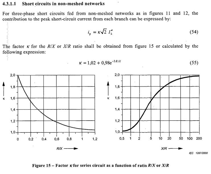
Based on k-factor = 1.8, I peak
= 1.8 x sqrt(2) x 37.28 kA
= 95.1 kA
Extra on k factor for peak current
===============
Note: Peak Current Multiplier comes from k x sqrt(2) = 1.8 * 1.4142 = 2.55
In this case, k selected is 1.8 based on X/R ratio of 14. The selection is based on Figure 15 in IEC 60909.
2. Former WRONG Answer - 3 phase short circuit calculation using MVA or per unit method.
Utility MVA
= 50kA * 11kV * sqrt (3)
= 50kA * 11kV * sqrt (3)
= 952.63 MVA
Tx MVA
= 1500kVA/5.65*100
= 1500kVA/5.65*100
= 26.55 MVA
Cable Z
= 0.1 km * Z
= 0.1 km * Z
= 0.1 * sqrt(0.0751^2 + 0.3342^2)
= 0.034253ohm
Cable MVA
= V^2/Z
= 0.4^2/Z
= 4.671 MVA
Cable MVA
= V^2/Z
= 0.4^2/Z
= 4.671 MVA
Let MVAsc be the equivalent fault level at point of fault,
1/ MVAsc
= 1/MVAutility + 1/MVAtx + 1/MVAcable
= 0.2528
MVAsc
= 1/0.2528
= 3.956 MVA
Isc ................................3 phase fault
= MVAsc/(sqrt(3) *V)
= 3.956/(1.732 * 0.4)
= 5.7 kA
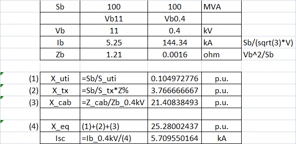
Per Unit Method


No comments:
Post a Comment